
TM 11-6625-596-12
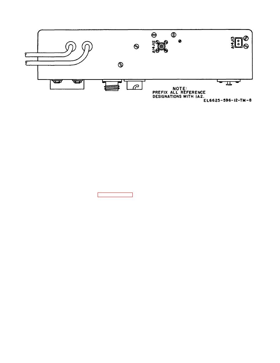
Figure 2-2. Electrical test panel 1A2A14, top view.
Section II. OPERATOR'S CONTROLS AND INDICATORS
2-7. Damage From Improper Settings
2-8. Telephone Test Set TS-716/U
(fig. 5-1)
Operating Controls and Indicators
CAUTION
(fig. 5-1)
Before applying power to Telephone
a.
The pushbutton switches on the left side of the
Test Set TS-716/U, set the front panel
front panel, consisting of two vertical rows of eight
controls to the positions indicated below.
buttons each, are of the interlocking type. Fully
This will prevent the possibility of
depressing any button of this switch causes that switch
overloading the panel meter and
section to lock in its depressed position and
damaging the transistor power amplifier.
automatically releases any other button, in either row,
a.
The guardplate on the power switch must be
that has been previously depressed. Thus/no two buttons
correctly positioned as described in paragraph 2-5
can be simultaneously locked in the depressed position.
Connecting the TS-716/U to the incorrect line voltage
If it is required that all buttons of these switches be in
may cause damage to the power transformer.
their released positions, this may be achieved by partially
depressing any button in either row that is not
b.
The preliminary control settings are as follows
depressed. Upon release, both it and the button that
Control or switch Setting
was locked in the depressed position will be released.
Power ...........................................................OFF
NOISE GEN ADJ..........................................Depressed
b.
The pushbutton switches located near the
CALIBRATE:
center of the panel consist of six buttons in a vertical row
a
NOISE GENERATOR..............................Fully ccw
and another vertical group of two buttons, of momentary
METER SENSITIVITY .............................Fully cw
action switches which must be held in the depressed
INSULATION RESISTANCE ...................Fully ccw
position when they are in use.
DIAL SPEED ...........................................Fully ccw
DIAL BREAK ...........................................Fully ccw
c.The operating controls, indicators, and fuses, as
NOISE GENERATOR ..................................LOAD
well as their functions, are listed in the following chart.
TEST CONDITION .......................................COUPLER
MICROPHONE LOAD ..................................OFF
RECEIVER LOAD ........................................OFF
MICROPHONE CURRENT ..........................OFF
a
Counterclockwise
2-4


 Previous Page
