
TM 11-6625-648-12
4-4. Organizational Quarterly Preventive Maintenance Checks and Service Chart
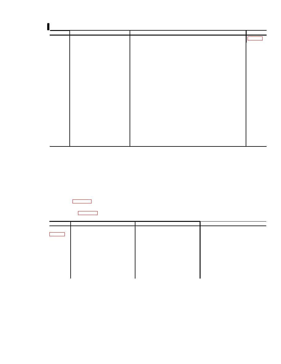
Procedure
Item to be inspected
Sequence No.
References
a. Obtain a spare operable CX-4245/G of known length ( mile ap-
1 ........
BRIDGE test circuit . . . . . . . . . . . .
prox) and connect it to the TS-1323/PTM-7 for a capacitance test.
Conduct the test and compare the results with the actual length,
allowing an error of 250 feet.
Compare the results with the actual length of the CX-4245/G,
allowing an error of 250 feet.
2........
Order-wire probe . . . . . . . . . . . . . . .
a. Carry the TS-1323/PTM-7 to the closest TD-206/G known to be
carrying pcm traffic and insert the order-wire probe into a lightning
arrester well in the TD-206/G. Connect the order-wire probe to
the TS-1323/PTM-7; pull out the BATTERY POWER switch, and
operate the BUZZER switch to ON.
b. Operate the ORDERWIRE switch to SIG momentarily. Note that the
CALL lamp becomes illuminated and the buzzer sounds. A 1,600-
cps tone should also be heard.
c. Operate the ORDERWIRE switch to TALK, and request that the
operator on one end call back. On the call back, note that the
CALL lamp becomes illuminated and the buzzer sounds. Note that
the CALL lamp does not flicker while you are talking.
3 . . . . . . . . . Pcm probe . . . . . . . . . . . . . . . . . . . .
Attach the pcm probe to the PROBE connector on the TS-1323/PTM-7.
Operate the METER SELECT switch to PROBE. Insert the probe into
the lightning arrester well of the TD-206/G. Note that the TEST
METER shows a pronounced deflection. The meter pointer should
reach at least 1 on the scale.
Section Il. TROUBLESHOOTING
4-5. Troubleshooting Chart
until an abnormal condition or result is observed.
When an abnormal condition or result is observed,
Troubleshooting is based on the operational checks
note the sequence number and turn to the correspond-
contained in the preventive maintenance checks and
ing item number in the troubleshooting chart. Perform
services chart. To troubleshoot the equipment, per-
t h e checks and corrective actions indicated in the
form all functions in sequence numbers 7, 8, and 9 in
troubleshooting chart. If the corrective measures indi-
the weekly preventive maintenance checks and ser-
cated do not result in correction of the trouble, higher
vices chart (para 4-2) and sequence numbers 1, 2, and
category maintenance is required.
3 in the quarterly preventive maintenance checks and
services chart (para 4-4). Proceed through the items
Item No.
Trouble symptom
Probable trouble
(Checks and corrective measures
Weak batteries . . . . . . . . . . . . . . . .. . .
Replace batteries.
a. TEST METER fails to indicate in
1
green zone.
Rubber bumper does not engage the
b. BATTERY POWER switch does
Check for presence of rubber bumper.
not depress when case cover is
Check to determine that case cover
BATTERY POWER switch.
fully closes.
closed.
Signaling oscillator, signaling detector, Higher category maintenance is required.
2 ........
CALL indicator lamp fails to become il-
luminated and buzzer fails to sound.
or signaling amplifier is faulty.
BUZZER ON-OFF switch or buzzer is Higher category maintenance is required.
CALL indicator lamp becomes illumi-
nated but buzzer fails to sound.
defective.
Replace indicator lamp.
CALL indicator lamp is defective.
Buzzer sounds but CALL indicator
lamp fails to become illuminated.
Change 4
4-3


 Previous Page
