
TM 11-6265-596-45
be less than 90 dB above a reference level of 0.0002
(+1 dB) from at least 100 to 10, 000 Hertz and must be
microbar, when 10 milliwatts rms power is
capable of measuring voltage from 0.001 rms to 100
applied to the driver terminals.
volts or more.
f.
Measurements should be performed in a
b.
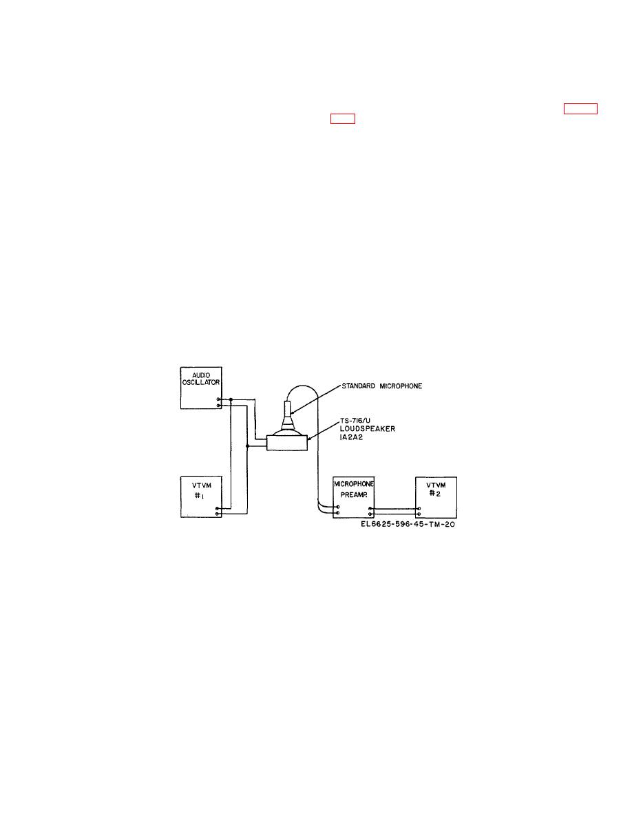
Connect the equipment as shown in figure
rela-tively free sound field.
6-21.
Coupler Microphone Frequency
Response
c. Position the coupler microphone so that it
Test
is located 1/8 inch directly in front of and parallel to the
calibrated driver.
a. Test Equipment. The test equipment used
for the response test shall meet the following
requirements.
7.0 ohms across the microphone output.
(1) Calibrated driver unit.
Western
Electric Company, Type No. 555W, or equal, previously
e. Output power of the driver unit shall not be
calibrated by means of a condenser microphone such as
less than 28 microbars at the screen of the driver unit.
Western Electric Company 640AA, or equal (calibrated
Minimum power output of the microphone shall be -50
by " eciprocity Method" in accordance with A. S. A.
R
dBm at 1, 000 Hertz, equivalent to 0.27 millivolt across
Standard
Z24.4-1949
" ressure
P
of
a 7.0-ohm load.
Laboratory Standard Pressure Microphones" .
)
(2) Audio oscillator. The audio oscillator
f.
Data shall be taken in 100-Hertz
shall have a frequency range of at least 100 to 10,
increments from 300 Hertz to 1, 000 Hertz, and in 250-
000' ertz, shall have a high degree of stability in both
H
Hertz increments from 1, 000 Hertz to 5, 100 Hertz.
output voltage and frequency, and shall have a
waveform distortion of less than 2 percent.
g. The data obtained in f above must fall
within the limits of +3 dB centered at 1, 000-Hertz
reference level.
tube voltmeters used must have flat frequency response
Figure 6-5. Driver frequency response test setup.
6-7


 Previous Page
