
TM 11-6625-596-45
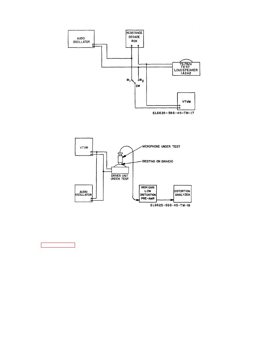
Figure 6-2. Driver impedance test setup.
Figure 6-3. Coupler/driver unit distortion test setup.
c. Connect the output of the audio oscillator to
6-9.
Microphone
Frequency
Response and Gain Test
MICROPHONES-OTHER TYPES terminal 1A4E3 and
LO terminal 1A4E2.
a. Set the TS-716/U front panel controls as
specified in paragraph 6-4 except for LEVEL and
d.
Set oscillator frequency to 1, 000 Hertz.
VALUE controls 1A4T1 through 1A4AT4, which must be
set at 0.
e. Connect the vtvm to terminals 1A3J1-L and
1A3J1-K (ground), and adjust the oscillator output to
b. Set TEST CONDITION switch 1A4S9 to
produce a reading of 300 microvolts on the vtvm. Hold
ART REC, and MICROPHONE LOAD switch 1A4S1 to
this reading constant over the frequency range specified
1000, Depress SOUND POWER TELE-PHONE button
in g below.
1A4S6H.
6-3


 Previous Page
