
TM 11-6625-596-45
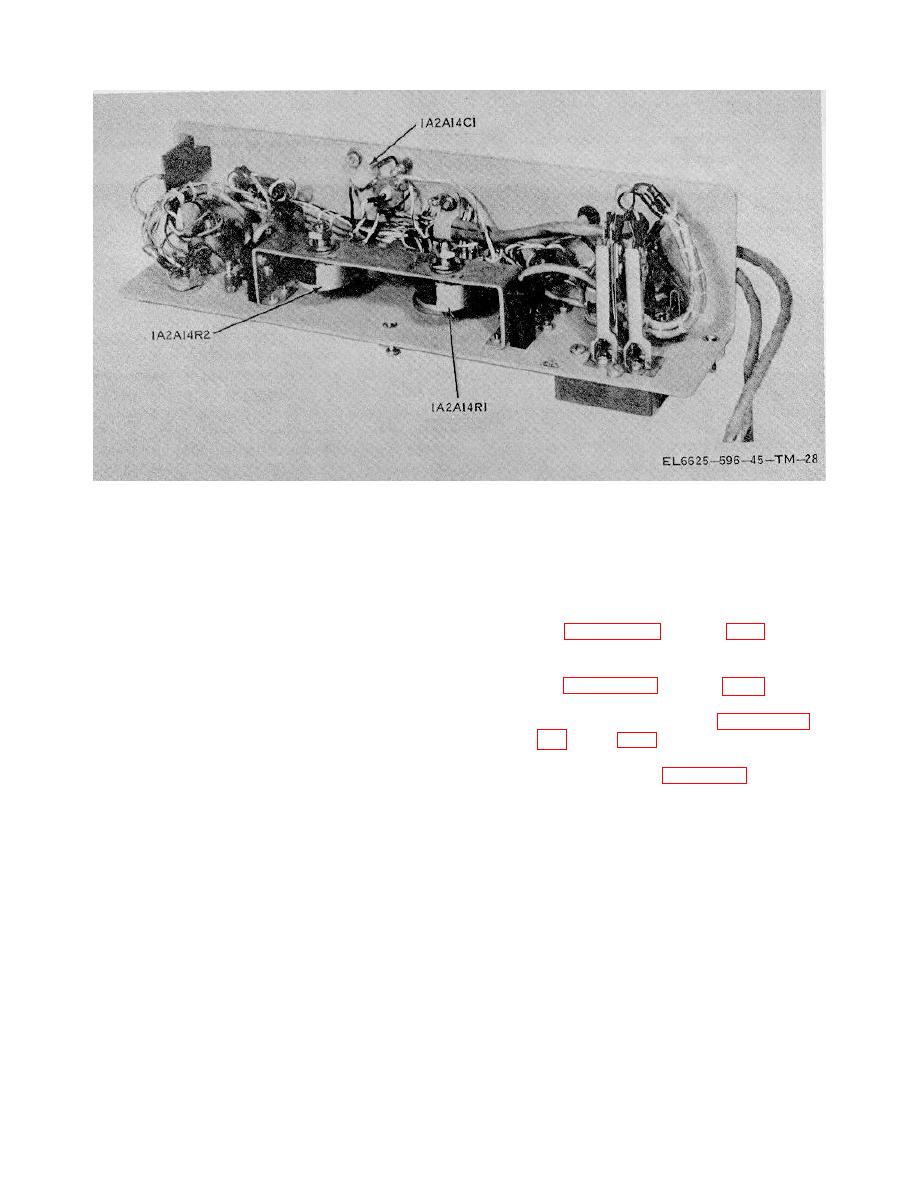
Figure 3-6. Electrical test panel 1A2A14, bottom view.
multimeter to check the voltage at that point. If the
direction, remove the printed circuit
signal or voltage is not present, the third column lists the
boards before making tests. The
steps to be taken to localize the fault. Make all
controls, connectors, piece parts,
continuity checks and short circuit tests with the
and plug-in assemblies cited in the
voltohmmeter. Turn off the power to the test set during
troubleshooting chart are called out
these tests. Do not attempt to use the continuity test
on figures 3-1 through 3-6.
The
circuit of the test set for making continuity tests.
piece parts on plug-in assemblies
1A3A1 through 1A3A10 are called out
CAUTION
on figures 3-7 through 3-16. The
The test set contains many polarized
terminals on switches 1A4S5, S6,
tantalum
electrolytic
capacitors.
and S7 are called out on figures 3-17,
Applying a voltage of the wrong
Pin
polarity to these capacitors will
locations on 1A3J1 through 1A3J10
damage or destroy them. Always
are illustrated on figure 6-10.
make continuity or short-circuit
checks in the direction given in the
instructions. If in doubt about the
3-7


 Previous Page
