
TB11-6625-596-12/1
2. Do not cover the microphone port with the
NOTES
holding
1. Tape the microphone switch to ON while testing.
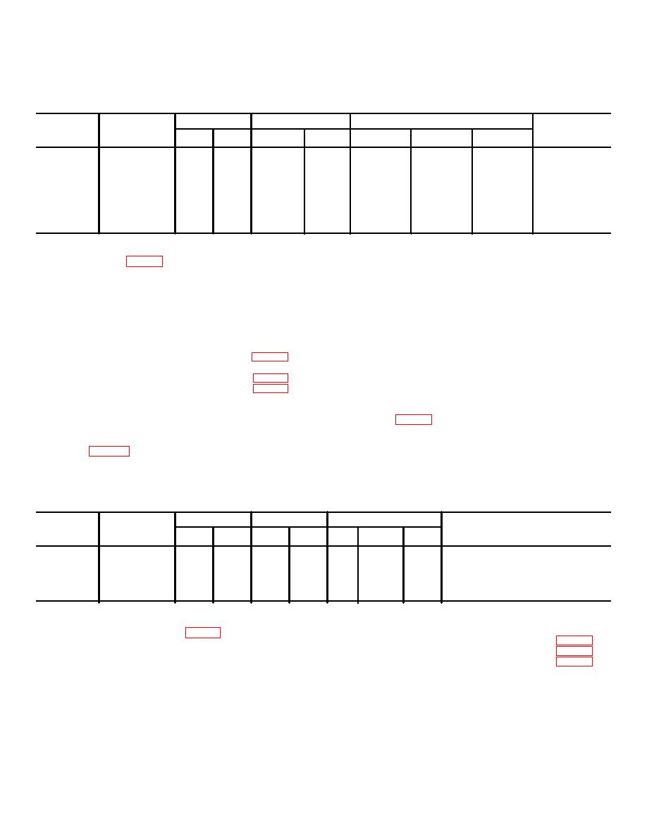
Table 2. Norms for Dynamic Microphones
MICROPHONE
LEVEL controls
VALUE controls
Meter Limits
Microphone
LOAD
Notes
switch
A
B
C
D
LOW
CENTER
HIGH
M-30/U
150
20
4
12
16
35-70
35-65
35-65
1A2A14JI
M-WOC/GR
150
20
6
11
12
35-66
40-60
40-65
1A2A14J7
M-87/AIC
4
10
4
6
17
30-70
35-75
30-60
Cable D
M-105/U
50K
30
2
10
16
35-80
40-60
35-70
Cable E
M-16/G
150
10
8
14
16
30-72
30-70
35-70
Cable A
M-133/U
4
10
6
14
18
30-75
35-65
30-60
1A2A14J9
M-136/U
150
20
3
10
1
30-65
35-65
35-65
1A2A14J7
M-138/G
150
20
2
1I
16s
25-75
30-70
40-65
Cable A
e. Shake the microphone vigorously.
8. Carbon Microphones Test. a. Perform the
f. Position the microphone unit squarely over the
starting procedure (para 5).
b. Set the front panel controls as follows:
test loudspeaker screen. Hold the microphone in place
by using the clamping fixture.
NOTES
Control
Setting
1. Tape the microphone switch on ON
BATTERY switch .............................................. Any.
while testing.
TEST CONDITION switch................................. ART REC.
2. Do not cover the microphone port
NOISE GENERATOR switch ............................ DRIVER.
with the holding fixture.
MICROPHONES CARBON button.................... Depressed.
g. Press the READ MICROPHONE CURRENT
MICROPHONES CURRENT control................. OFF.
button and adjust the MICROPHONE CURRENT control
MICROPHONE LOAD switch............................ See table 3.
until the meter reads midscale. (Press the READ
RECEIVER LOAD switch .................................. OFF.
MICROPHONE CURRENT button two or three times
LEVEL A and B center ...................................... See table 3.
until the current stabilizes.).
VALUE C and D controls .................................. See table 3.
c. The meter should read midscale. If the meter
h. Press the LOW, CENTER, and HIGH buttons in
does not read midscale, adjust the METER
sequence. The meter should read within meter limits
indicated in table 3 for each condition.
SENSITIVITY CALIBRATE control for midscale reading.
d. Connect the microphone plug into jack
i. If the microphone fails the test, repeat the test.
Some carbon microphones fluctuate considerably.
1A2Al4J1, 1A2A14J5, or 1A2A14J6. See the Note
column in table 3 for the specific jack and/or special
cable and adaptor plate required for the particular item to
be tested. Connect the special cable leads to the
MICROPHONE CARBON front panel terminal.
Table 3. Norms for Carbon Microphones
MICROPHONE
LEVEL controls
VALUE controls
Meter Limits
Carbon
LOAD
Notes
Microphone
switch
A
B
C
D
LOW CENTER
HIGH
M-29B/U
40
50
8
8
7
40-88 40-96
40-96
1A2A14J6
M-35/U
40
70
4
11
12
30-60 30-60
30-60
Use H33F/PTas Fixture A2A14J6.
M-51/UR
40
60
6
4
4
35-75 35-80
35-75
Use M52/U as Fixture 1A2A14J1.
M-52/U
40
60
2
7
6
34-80 35-86
35-86
1A2A14J1
T-4
40
60
0
4
9
40-75 45-75
40-70
1A2A14J5
Control
Setting
a.
9. Earphones, Receiver, and Headsets Test.
MICROPHONE LOAD switch ...........................OFF.
Perform the starting procedure (para 5).
RECEIVER LOAD switch ..................................See table 4.
b. Set the front panel controls as follows:
LEVEL A and B controls ...................................See table 4.
VALUE C and D controls ..................................See table 4.
Control
Setting
c. The meter should read midscale. If the meter
BATTERY switch .............................................. Any.
does not read midscale, adjust the METER
MICROPHONE CURRENT control ................... OFF.
SENSITIVITY CALIBRATE control for a midscale
TEST CONDITION switch................................. COUPLER.
reading.
NOISE GENERATOR switch ............................ LOAD.
EARPHONES button ........................................ Depressed .
d. Plug the earphone into jack 1A2A14J6,
1A2A1417, or 1A2A14J8. See the Notes column in
4


 Previous Page
